


Adjusting camshaft center lines on a big turbo Audi
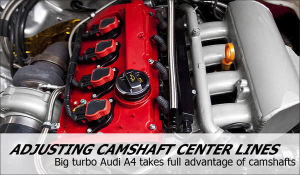
Adjusting camshafts center lines on a big turbo Audi A4
Recently we posted a DIY on how to advance or retard your cam timing using an Integrated Engineering billet adjustable cam gear to show you the steps and effects of doing so. The results were dramatic, check out the complete DIY and dyno results here. In this article, we are going to take cam adjustment one step further and change both intake and exhaust cam center lines on an Audi A4 equipped with Integrated Engineering CVA1 camshafts.

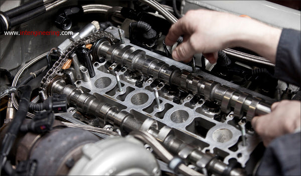
Making adjustments to the cam centerlines requires more in-depth work than adjusting the cam gear alone. It necessitates the installation of a cam degree wheel, which generally requires removal of the crank damper and the main damper bolt... Having a spare long block removed from a car makes this much easier, so we began by gaining access to the cam shafts.

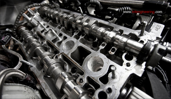
The camshafts are being totally removed from the car.

From here we set up the spare long block with the proper tools to degree cams. First, the crank is outfitted with a degree wheel, and a small degree indicator was bent up out of some TIG welding rod. A piston stop such as COMP Cams part number 4795 is required to set the degree wheel to true TDC. This is accomplished by rotating the degree wheel all the way one direction until the piston hits the piston stop. Record the degree number, then rotate the crankshaft all the way the other direction. Adjust the wheel until these two numbers are identical, putting TDC directly in the center, then remove the piston stop. This ensures the degree wheel is much more accurately aligned to the crankshaft journals then simply using the OE marks.

Then the camshafts are installed into the head.
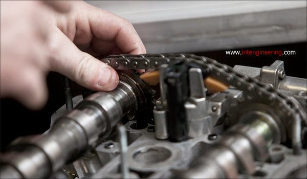

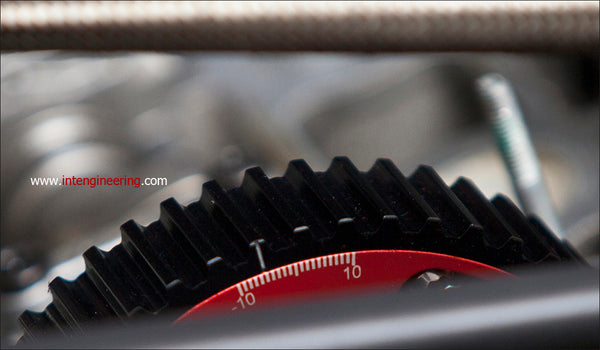
The exhaust cam will be degreed in using an Integrated Engineering billet adjustable cam gear. To keep the new cam gear secure during high RPM's an IE/EKagrip friction shim disc and IE/ARP cam gear bolt are used. It's important to make sure you have installed a cam seal as well as properly torqued the cam bolt. It will not be removed again, in order to preserve accuracy.

With the cams installed, a dial indicator with a magnetic base is positioned onto a lifter bucket on cylinder number 1. Our dial indicator uses a carefully bent wire to loop around the camshaft and rest on the lifter bucket. Alternatively, you can use our cam degree blocks (Part Number: IETLVA2) which install on the #4 cylinder and allow direct access to lift measurements.

The cam is now ready to be degreed.

The center line angle is expressed as the number of crankshaft degrees from TDC to max camshaft lift (centerline of the lobe). The exhaust camshaft centerline angle occurs from 100 to 120 degrees before TDC. The intake camshaft about 100 to 120 degrees after TDC. By changing the camshaft center lines, one can shape the power curve, as well as influence factors like intake and exhaust reversion, intake charge ramming, exhaust blow down, and many others. We begin with the exhaust cam since it's position changes the position of the inlet camshaft on most VW / Audi engines. The dial indicator is used to find the camshaft centerline angle and confirm changes made at the cam pulley.

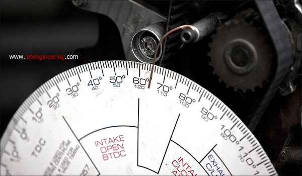
As the engine is rotated over towards the relevant camshaft's peak lift, and the camshaft starts lifting the valve, we pick a lift measurement to take a crankshaft angle reading at. There are many heights people use, but for simplicity I recommend using a lift level near the middle of the lift of the camshaft, like .200" of lift. If you measure at too low of a lift, it puts the measurements more then 180 crankshaft degrees from the centerline angle, and this is a pain with most degree wheels. If the cam lobe appears asymetrical, check with your camshaft grinder as to what height you should be measuring at. As you are rotating the crankshaft in the direction of engine rotation (normally clockwise), stop rotating when the dial indicator has reached your chosen lift level. Record the crank position it is currently reading- in this case, about 65 degrees. Continue to rotate the engine, through maximum camshaft lift, and back down until the camshaft lift is once again at your baseline lift number. Again, record the crankshaft position. Now, you should have two numbers, like 65 degrees, and 151 degrees. Taking the average of these numbers gives the installed centerline angle for that particular cam lobe. For example, 65 + 151, divided by 2, gives a centerline of 108 degrees. Adjust the cam gear to get the lobe centerline angle you desire, and continue verifying that centerline angle until you are satisfied of its location and the accuracy of your measurement.

With the desired exhaust centerline reached, we turned our attention to the intake cam. The setup process is the same, set the dial indicator up on an intake cam lobe and pick a cam degree and crankshaft degree reference point.

Beginning with our reference numbers, we repeat the process. Now the process changes, there is no adjustable cam gear for the intake. There are two ways to tackle this- one is to install an adjustable cam sprocket on the back of the camshaft. These typically have slots and small bolts which allow you to quickly and accurately change the intake centerline. For these, the easiest way on a 1.8T 20V engine is to install that sprocket on the exhaust side, as the access to those bolts is much better then on the intake side. It does not matter which of the two sprockets you adjust, the effect is the same. The other method is somewhat more tedious, but the effect is the same. That is to mark the standard sprocket and the camshaft for alignment, press the sprocket off, then press fit it back in place in a new position. Since this process is pretty hard on the components, we recommend welding the sprocket in place after the correct centerline angle is achieved. These engines have a nasty history of spinning the cam chain sprockets on the camshafts to start with, and the results are not pretty.

With the camshafts now properly degreed to the desired setting, they are re-installed into the original engine.


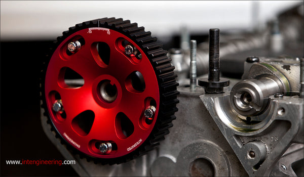
The only visual change will be the new cam gear displaying the new exhaust cam degree.

With the cams fully installed and the engine buttoned back up its time to start the engine.

The new cam centerlines for this engine was a complete success, the idle was much smoother and car had increased vacuum. The owner explains that this was the best power modification since installing cams, and really woke up the car. "The difference on the car is amazing. Absolutely amazing. First off, my car idles beautiful, and it gained a highly noticeable difference in mid RPM power and torque. The car pulls MUCH harder and boost does not taper, it pulls hard all the way to 8500+ RPM and shows no signs of tapering off. I lost no noticeable amounts of initial spool nor did re-spool suffer at all".
The new degreed cams moved the power band to the left, making more useable power in the mid - high RPM range instead of a higher peak power range in the upper RPM. This makes the car much more efficient as a street car with a more useable power band overall.
Parts used in this article: IEVTVA8 : Ultimate Cam Gear kit for 06A 1.8T Engines (PN IEVTVA9 for early 058 1.8t) Optional: IETLVA2 Cam Degree Blocks (for 1.8T 20v applications) COMP Cams # 4795 Piston Stop Generic Degree wheel Generic .001" increment dial indicator with magnetic base